


at least one thing turned out... I ended up putting a little tape on the threads that went from brass to stainless. they would not stop weeping. and it was to the point of thinking something might break, there was not any problem with stainless to aluminum. just stainless to brass, and as it is has been cranking over, I can smell gas.. so I am keeping my fingers crossed that it will be firing up with I figure out the electrical. o
on a side note, i put a pressure gauge on the one of the ports on the oil filter housing. and I haven't seen it move yet, almost thinking the oil pump might need a little priming. with just the 200 rpm cranking going on...
so I am feeding the injectors with 1/4" OD tubing, the supply and return are 3/8" OD pipe, and they tie into the stock flexible lines with 5/16" hose barbs.
 |
 |
Results 41 to 60 of 79
Thread: Efi retrofit for the 084 motor
-
06-19-2019, 03:02 AM #41Junior Member


- Join Date
- Dec 2015
- Location
- Valdez, Alaska
- Posts
- 574
Re: Efi retrofit for the 084 motor
Last edited by Bart; 06-19-2019 at 03:06 AM.
-
06-22-2019, 12:31 PM #42Junior Member
- Join Date
- Dec 2015
- Location
- Valdez, Alaska
- Posts
- 574
Re: Efi retrofit for the 084 motor
while I am waiting for some coils, I figured that even though I could smell gas, when cranking the motor over, I better is what was all happening. a couple of years ago I picked up a testing unit called PowerProbe 4, one of its funtions is to test the injectors, and it will give you the 4 needed readings, where the injectors only have 2 wires going to them, 12 volts power and the ground goes to the ECU. you just need to put the probe onto the wire going into the injector or where it ties into the ECU, crank or run the motor and you get the information..
the only thing that might be a small problem is the kickback voltage, I am reading that it should be between 55-90, and I am only getting 42 at the moment. but the battery is a little low. Also looking at the ECM ground voltage I see channel 1 is reading .015, where channel 2 is .09, both from what I am reading are still in spec.
I will be using only 2 of the 4 channels. " if/when there is a camshaft sensor, then each injector could have its own channel." but at the moment cylinders 1 & 2 will be on one, and 3 & 4 on the other.
It was good to verify that they are working.
once I get the motor running, a fuel map will be generated, and with the O2 sensor we will be able to get everything dialed in.
all the sensor are sending readings to the speeduino. "still working on the thermistor to get it dialed in."
on another side note, the silicone 1-3/8" tubing showed up. to replace the 60 year old intake tube rubber hose seals. it came in a 3 foot section. so I should have more than enough.
-
06-22-2019, 10:29 PM #43Super Moderator

- Join Date
- Jul 2014
- Location
- Susquehanna river, Dauphin, Pa
- Posts
- 1,303
Re: Efi retrofit for the 084 motor
Glad to see everything checked is within working range for the most part...Would the addition of the cam sensor be a worthwhile addition down the road ?? Does that silicone tubing have any structure to hold the weight of the upper intake joint and components {I'm wondering if it's a good replacement for old original seals for other applications} ??
Aluminum .120 14' X 76" hull
Teledyne 4a084-4 engine
Circle S 1.69:1 reduction
67" Whirlwind "Razor X" prop
-
06-23-2019, 01:56 AM #44Junior Member
- Join Date
- Dec 2015
- Location
- Valdez, Alaska
- Posts
- 574
Re: Efi retrofit for the 084 motor
according to the specs it should.. but time will tell, but it does have a better grip on the tubing, I just remember one time when cranking it over I didn't have a clamp overly tight and I could hear air getting sucked in. and now for all the times that I have assembled and disassembled the intakes, they are in pretty poor shape.. so almost anything is better. (the local store carried 1-7/16 hose, it was a little to big, but it is working great for a ball rest on the grandkids T-ball hitting stand.)
I was thinking that I only ordered a foot, but 3 feet showed up. and no extra charge. just had to wait the 3 weeks for shipping.
https://www.ebay.com/itm/35mm-1-38-inch-silicone-meter-hose-4-ply-silicone-intercooler-intake-hose-blue/283310780351?ssPageName=STRK%3AMEBIDX%3AIT&_trksid =p2057872.m2749.l2649
the 2 Mpa is equal to around 290 psi.
100% Brand New. Universal Product! Not Easy to break down or harden, more durable than the original . Perfect for DIY Turbo, Intercooler, Intake, Turbo Charger Projects! Accept higher pressure than the original . The temperature change will not affect the shape and the flow rate.
4 Layer Fiber Cloth . 5 Layer Polyester . 4.5mm Wall Thickness .Working Temperture:-70 degree to 280 degree . Hose Burst Pressure Limit Equal to 2 Mpa.. Working Pressure: 0.3 to 0.9Mpa. Our hose are streng then with the use of honey comb shaped textile fiber to with stand strong pressure while maintaining its shape,the silicone polymers material used are very durable and does not tear easily , all hoses come with 4 layers of honeycomb shape textile fiber and silicone polymer,We use the finest silicone polymers to ensure you get the best quality silicone hoses
-
06-23-2019, 03:27 AM #45Junior Member
- Join Date
- Dec 2015
- Location
- Valdez, Alaska
- Posts
- 574
Re: Efi retrofit for the 084 motor
from what I have learned about the cam sensor...it needs to be triggered once ever 720 degrees of motor rotation, where it is located and angle does not mater, Originally Posted by Corky

there could be room to mount a trigger wheel on front of the camshaft sprocket, but it would be tight.
on a side note I watched a video the other day, where someone embedded a magnet onto the camshaft wheel, and was using a hall sensor, and was able to make it work for what they were doing,
when I get time I want to look into this. if the speeduino board would pick up just one magnet, it would not take much to drill a small hole and epoxy a magnet on the camshaft gear,.. and punch a hole in the front of the cover, to install the sensor.
you got me thinking about this again.. but at the moment, if I could just use one anomaly on the wheel like an embeded magnet, it would be a simple thing. just need to see if that will register, there they like to see the missing tooth or optic sensors, at the moment.
below is what the speedy manual says about setting up the ignition & spark
- Wasted Spark - Number of ignition outputs is equal to have the number or cylinders and each output will fire once every crank revolution. One spark will therefore take place during the compression stroke and the other on the exhaust stroke (aka the 'wasted' spark). This method is common on many 80s and 90s vehicles that came with specific wasted spark coils, but can also be used with individual coils that are wired in pairs. Wasted spark will function with only a crank angle reference (Eg a missing tooth crank wheel with no cam signal)
- Single Channel - This mode sends all ignition pulses to IGN1 output and is used when the engine contains a distributor (Typically with a single coil). The number of output pulses per (crank) revolution is equal to half the number of cylinders.
- Wasted COP - This is a convenience mode that uses the same timing as the 'Wasted Spark' option, however each pulse is sent to 2 ignition outputs rather than one. These are paired IGN1/IGN3 and IGN2/IGN4 (ie When IGN1 is high, IGN3 will also be high). As this is still a wasted spark timing mode, only crank position is required and there will be 1 pulse per pair, per crank revolution. This mode can be useful in cases where there are 4 individual coils, but running full sequential is either not desired or not possible (Eg when no cam reference is available).
Up to 4 injectors
For 4 cylinders/injectors, there are 2 ways that these can be connected to Speeduino:
Method 1
The standard method is the same as that used for 6 or 8 cylinder setups, where 2 injectors are connected to each injector channel. In this configuration, only 2 injector channels will be used. The injectors paired together must have their Top Dead Centres (TDC) 360 crank degrees apart.
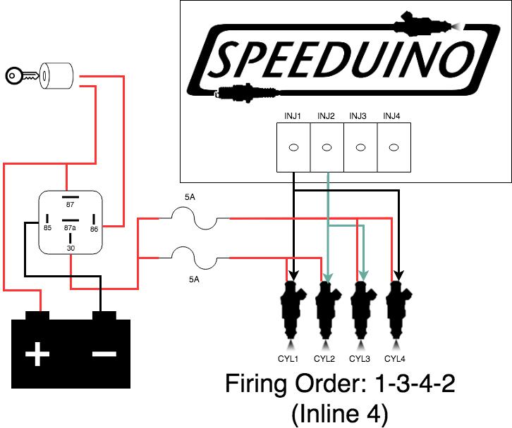
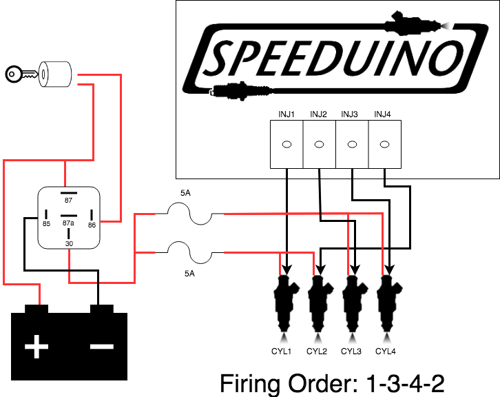
Method 2
This method is only available on 4 cylinder / 4 injector applications and allows you to wire 1 injector per channel. The injector channels always fire in numerical order (ie 1, 2, 3, 4) so your injectors should be wired to take your firing order into account. Within Tuner Studio, this option can be enabled by selecting:
Settings -> Engine Constants -> Injector Timing -> Semi-Sequential
from what I have read, if there was a cam sensor, then you could fine tune each cylinder, when you want it to spark, and other things, I need to read up on it again, before I put my foot in my mouth....
I was just thinking, though. I have a bung on each exhaust side. for the O2 sensor. if nothing else I will change the injector wiring from 1 & 2, and 3 & 4, to 1 & 3 and 2 & 4, that way at least if there is something weird on one side. I will be able to catch it. I just will not know which cylinder it is
it seems to me that there have been a few that have had a cylinder go down on them in the last couple of years, Bobby had one, but it was already down when he bought the motor, where the valve had enlarged the head..(that could have happened from a leaky gasket and the cylinder running to lean.)
when this gets going, I think I am going to like it with being able to fine tune it,
here are a couple of links to some videos. that can help explain the set up a little better
speeduino EMS #7 - Adv Trigger#2 - Crank w/IGN demo
https://www.youtube.com/watch?v=k6gEccn17Ro&t=26s
Speeduino EMS #8 - Adv Trigger#3 - Cam w/IGN demo
https://www.youtube.com/watch?v=vYRM0G9Z160&t=11s
Last edited by Bart; 06-23-2019 at 11:26 AM. Reason: added some learning videos about trigger and cam setup
-
07-03-2019, 01:13 PM #46Junior Member
- Join Date
- Dec 2015
- Location
- Valdez, Alaska
- Posts
- 574
Re: Efi retrofit for the 084 motor
HAPPY DAY.... IT IS ALIVE....


the new used coils came in the other day, and I had spark,.. but was not getting any fuel out of the injectors, spent just a few days going over all the data and perimeters that I had put into the system, so see what I had messed up on.
last night I just happened to look at the engine constants, and noticed that the injector open time was at .1 ms. then looking deeper I had the wrong box checked for lbs/hr or cc/min. upon checking the correct box cc/min. the open time went up to 6.1 ms.
uploaded the new data and life is great.....
i still have one problem injector, it will fire when forced
( plug one connector of the injector to 12 volts, and tap the other connector to a good ground, this will let you hear it click and if there is fuel pressure in the the line, it does come out)
but there might be a weak connection in the wiring. and need to put a timing light on it to verify the timing. but it starts right up after the 2 dead revolution cranks. and it sounds real nice.
there still is a lot of little things to do. but it was nice to see that this could be done. haven't opened the throttle past 20%. (need to get it out of the shed for that)
https://youtu.be/_OBK1HHzhi4
https://youtu.be/qlJ37RYeKY8
-
07-05-2019, 05:24 AM #47Junior Member
- Join Date
- Dec 2015
- Location
- Valdez, Alaska
- Posts
- 574
Re: Efi retrofit for the 084 motor
did some more testing on the motor. I took the time and changed the injectors to run semi sequential. that way each one has it own channel. as I was doing this, I noticed that the wire for channel 2 had some corrosion in it. so I cut it back to where the wire was good and soldered an extension to it. I am thinking that might have been why the one injector was not doing so well. I need to learn how to read the data log that the motor is producing. at the moment with a temp gun. cylinders 1 2 & 4 are running about the same and #3 is running about 50 degrees hotter.
also took time to plumb in an oil cooler today. the stock flywheel seems to be pushing enough air past the cylinders, it does get warm standing in front of the motor...
found out that some of the pins on the board are touchy. when I went out to start it up this morning. I wasn't getting any crank signal.. as I was going over and reading the resistance. The push pins that I was using to read the pins on the mother board, helped out and I had crank signal again. important note. always check the wiring connections , before digging deeper. the same thing happened with the stepper valve. when I started it up, it would rev up to 2400 rpm and the exhaust was getting hot. running a little lean..
it took a little to find the bad connection, still needing to work on the thermistor. I might just plug in a ford coolant sensor. where the speeduino has that data already entered into it. just having fun trying to find out what the bias value is... of the one that I put together. so the coolant reading is out of whack.
today a friends son stopped by and I found out that he has just a little more knowledge about the electrical part, of this hopefully I will get a couple hours of his time to help me understand the tuning part, and what I need to be looking for.
the main problem with tuning past an idle, is there is nothing that I can put a load on the motor. guess I better get that redrive finished up soon.
but I do like the sound of the exhaust. I will have to make another video tomorrow of it up and running. it is getting fun just to turn the key, after the 2 dead rotations. the motor comes to life. today was the most it has ran since I purchased it 3 years ago. I kind of think it was worth the wait.
it has been a fun journey from the different types of intake manifolds and all the other ideas that I have been doing to it. also I need to take time and see what the charging system is doing.
so there is a lot still going on with this, but this is the fun part, as soon as I start to understand more of the tuning aspect.
it was good to see that the one big question. If the magnets on the rope pulley would create to much noise for the crankshaft sensor, as our friend stated in his EFI build. but so far it has not had any effect on this set up.
the other bonus with running the injectors on their own channel. when I learn how, a person can manipulate the constants for each injector, to have all the cylinders running the same. and if I had a cam sensor, I would be able to do the same with the spark, if one cylinder needed it to be retarded or advanced. just a little different from the others.
o the possibilities. from the pictures, that I took using my powerprobe to get the injector data, they are all looking real close. the numbers jump around a little, but everything is looking good, at least I think so.Last edited by Bart; 07-05-2019 at 06:07 AM.
-
07-05-2019, 10:48 AM #48Member
- Join Date
- Aug 2015
- Posts
- 328
Re: Efi retrofit for the 084 motor
For what ever reason # 3 seem to be the hot cylinder .
On my VW motor #3 is the hot one too.
I put the temp sender ring under #3 plug.
-
07-05-2019, 02:28 PM #49Junior Member
- Join Date
- Dec 2015
- Location
- Valdez, Alaska
- Posts
- 574
Re: Efi retrofit for the 084 motor
that is some good information. makes a person wonder if the timing for when the spark plug fires for the #3 cylinder, if it is a little off, when compared to the other cylinders. Originally Posted by Coyotes-R-Us
before with just the carb, and the crapy stock casting of the intake on the 4A084, I could see where the lack of fuel getting to the 2 back cylinders would be a problem. but being next to the flywheel fan, it would dissipate the heat faster
now that I know what fuel is actually going to that cylinder, I will see what can be done to change things up, got a lot to learn now about changing the perimeters with this system.
I have 3 temp senders and only 2 gauges at the moment, but I will compare # 3 with the others. and let you know.
right now I might have about 2 hours of run time on the motor, just going over things and checking a lot of the little variables. it has been so bright out, that it has been hard to really verify the timing, with a timing light. it is close, but that is all I can see. even put white paint on the timing mark.
I am starting to wish that the redrive was finished, so I could put a load on the motor, and see what it does then...
last night I was looking at another web page, about where one used the SDS EFI & electronic ignition, and put it on his 4A084 airplane motor last fall, it was mentioned that he is finding that he has about 20% more static thrust. but they never did give out any readings.
https://www.homebuiltairplanes.com/f...llation.30615/
the next problem that I need to get taken care of, is the thermistor, with the data inputs that I entered, it was giving me an reading of 180 degrees, when cold. maybe i need to learn how to read the resistance properly? and still trying to figure out what the bias value is of it...
at the moment, there are about 10 different data points already entered in for the common manufactures water temps, and I have been entering them in to see if the readings are somewhat in the ball park.
i have a water sensor from a ford, that would work, but I dont know what the high temp is for it. where these motor heads at least under the spark plugs can get in the 475 degree range, "I just don't see a water sensor set up for that high of a heat"
just a few things to figure out, but it has been a fun journey so far.
-
07-05-2019, 04:45 PM #50Member
- Join Date
- Aug 2015
- Posts
- 328
Re: Efi retrofit for the 084 motor
Performance built vw's have a cam shaft that is a smidgen different for #3 , that address the problem I have read.
-
07-05-2019, 05:56 PM #51Junior Member
- Join Date
- Dec 2015
- Location
- Valdez, Alaska
- Posts
- 574
Re: Efi retrofit for the 084 motor
that is another way to "skin the cat" and sounds better than getting the vw to change the spark perimeters. I will need to read up on it, Originally Posted by Coyotes-R-Us
thanks for the Info.
-
07-06-2019, 12:35 AM #52Junior Member
- Join Date
- Dec 2015
- Location
- Valdez, Alaska
- Posts
- 574
Re: Efi retrofit for the 084 motor
just had to look and see it run some more, you can't tell that I am excited, until a few minutes ago I realized that I had the oil lines feeding the oil filter backwards....
 but with fresh oil, and filter, there doesn't look to be any damage.
I will know for sure, when I pull out the canister and see if any parts are missing...
tomorrow I have combined with some of the younger generation, one who is up on vacation, that writes codes for systems like this, and hopefully I will be able to retain some of the knowledge that will be shared. at least if I know how to look it up. that will be better than what I know know...
still just using a IR gun to look at the head temps. near the spark plug, with out being able to put a load on it. and knowing how to read the data charts. on how to rich or lean the injector VE table. I am content with just an idle. as you can see there is just a little difference in the head temp at idle. and at the moment it will change from one bank to an other. so I got a lot to learn..
on a side note in the video, it will focus on the blue box that the speeduino is in, the 4 LED lights that are opposite of each other in banks of 2 each, those are the injectors firing, and the 2 LED lights more in the center are the coils, if I put the coils each on their own channel I would have 4 LED lights in that area also.. these lights are a good help. the other morning they were not flashing, after I had added a couple of wires for the injectors, this told me that I had no crank signal, which gave me a good place to start trouble shooting
also I turned the key off, and restarted it. it is set up for 2 full cycles with no spark or fuel to give the brain time to get organized. down the road, this variable can be changed to what ever you want, but it is recommended to have 2 dead cycles. so it will be able to register the missing tooth, at least that i what I have read...
https://youtu.be/jeVx1F1zQfELast edited by Bart; 07-06-2019 at 12:55 AM.
-
07-14-2019, 10:07 PM #53Junior Member
- Join Date
- Dec 2015
- Location
- Valdez, Alaska
- Posts
- 574
Re: Efi retrofit for the 084 motor
so last week, I went out to do some tuning on the motor, it started running a little off key, to say the least cylinder 1 was up to 300, #3 was 250, and 2 & 4 were barely over 120 degrees, which makes it real difficult when the O2 sensor is on the 2 & 4 exhaust. I spent a few days looking and thinking about the different possibilities, or what to look at,
a lot on this project is now on the getting it dialed in and tuned stage.
my first thought was that there might be a intake leak, "to used to 2 stroke motors, when there is an intake leak, that cylinder will get hot and run lean, "
but 4 stroke motors are just a little different, so time to change the thinking.
so first off, I figured I needed to look at the injectors, up until now I really haven't done anything with an injector, but I got a little schooled up on them this last week
watched a couple of videos on how to clean them or see if they are working okay.
https://www.youtube.com/watch?v=rUUgR94drxg
I just was not talented enough to hold things like the video, so I made 2 discs to hold the tire valve to the injector, I would recommend wearing glasses, once in a while the red tube would come free from the spray nozzle. other than that, it worked great.
.
there was some dirt in all of the injectors, enough that #'s 2 & 4, I had to switch sides a couple of times. before I could get any fluid to spray through them.
It kind of surprised me that there was enough blocking them, that they would not even open up. but they all are working now.
I just hope that with the filter in place, the injectors will stay working from here on out.
the last picture is of the junk that was flushed out of just one of the injectors.Last edited by Bart; 07-15-2019 at 12:27 AM.
-
07-15-2019, 12:33 PM #54Junior Member
- Join Date
- Dec 2015
- Location
- Valdez, Alaska
- Posts
- 574
Re: Efi retrofit for the 084 motor
some more entertainment with the thermistor that I was having, was not understanding where the decimal needed to be when I was reading the resistance in Ohms.
I had taken quite a few readings from placing it in the freezer to boiling water, but when I had entered the numbers into the tunerstudio page, I was getting a reading of 180 degrees, at outside temp. so I had a friend so me the error of my ways, and explain where I went wrong, so now after moving the decimal to the correct place. the homemade thermistor is functioning like it should.
sometime it would be fun to see if it would work with an mechanical gauge. or what I would need to do, to make this happen.
I have also been able to go in and adjust the perimeters on a few of the gauges, so that they would be able to work closer with the readings that the 048 motor.
a few differences are turning down the max RPM's to 5000, and changing the coolant temp to Head Temp. and changing the degrees to go up to 500. then I added a air/fuel gauge,
I still need to see what I need to do to add at least 1 more head temp sensor & gauge,
I know to some, tracking all this data might be overkill, but it sure helps with the fine tuning, and really knowing what this motor is doing. and be able to adjust it accordingly.
-
07-17-2019, 02:09 AM #55Junior Member
- Join Date
- Dec 2015
- Location
- Valdez, Alaska
- Posts
- 574
Re: Efi retrofit for the 084 motor
I have been having fun and looking at different options as to where I want the coils located. It is kind of fun to have a few different options to look at. I am kind of liking this option with 2 coils mounted on a cylinder head. they are about 1/2" off of the valve cover. and so far there doesn't seem to be to much problem with any heat transfer.
with this setup, I don't need to worry about the plug wires coming in contact with the exhaust pipes.
maybe when this is all over and done with, I will put them under the oil pan, looking at ways to keep the wiring simple and clean.
-
07-18-2019, 10:47 PM #56Junior Member
- Join Date
- Dec 2015
- Location
- Valdez, Alaska
- Posts
- 574
Re: Efi retrofit for the 084 motor
I feel like I have been chasing my tail, the last few days...
went through and cleaned out the injectors,
changed out the mounting location for the coils & using some stock wires. there was just goofy about the new aftermarket wires. I have been fighting cylinders 2 & 4 for the last week.
and now after all this I am just fighting with cylinder #2,
to have a cylinder fire, you need 3 things, compression, spark, & fuel.
checked out the compression and all cylinders are at 120 psi
pulled out the injector last night, for a little bit, I couldn't get any clicking or fuel to pass though it. finally after a little bit, it started working again. put it back on the motor. pressurized the fuel lines, and when I shorted it out, the fuel pressure would drop. so it was working
and there is good spark.." at least that is what the timing light is telling me. and I did put in a new plug, and there is spark.."
now the fun
when I started it up this morning, #2 head warmed up to 150 degrees, gave it a little throttle. and it went cold. back to 110 degrees,
per the timing light, there is good spark,
ordered some more injectors,,
thinking of turning out another injector bung, just so I could actually see if this injector is the problem child.
thinking that the wires to the injector might be the problem, I swapped 2 & 4, and it stayed the same, cylinder 2 was still dead,
I might just go out and swap the injectors, at least that would tell me if I am barking up the wrong tree,
" the injectors are programmed to fire twice per firing cycle or once ever 360 degrees."
where I have good compression, I would think this would rule out floating valves, or bad rings.
when I had the O2 sensor on the 2 & 4 bank, it would run lean between 17 & 18,
now that I put it on the 1 & 3 pipes, it is running between 13 & 15
also with an IR gun on the exhaust pipe, #2 is staying a cool 110 degrees for the most part. "I did get just a little excited when it climbed up to 150 this morning for just a few minutes,"
anyway, this is just some of the entertainment that I have been playing with, hopefully I can get it figured out before to long,
other than this, everything else seems to be working great,
If anyone has any ideas. I am open for suggestions
-
07-23-2019, 09:57 PM #57Junior Member
- Join Date
- Dec 2015
- Location
- Valdez, Alaska
- Posts
- 574
Re: Efi retrofit for the 084 motor
Happy Day, the injector came today,
I ended up doing a little mod on the #2 injector bung also.. when I went to install the injector, it was to tight to push in. so I went to the lathe and opened it up another .0025", it still fits like a glove,
now in the back of my head, I am thinking that maybe if the bung was that tight on the injector, maybe the was just enough pressure on the housing to hinder it from opening up freely? Just a thought.
but the motor is up and running. and it is hitting on all 4 cylinder, and sounds real nice,
can't wait to get on with the tuning,
-
07-23-2019, 10:33 PM #58Super Moderator
- Join Date
- Jul 2014
- Location
- Susquehanna river, Dauphin, Pa
- Posts
- 1,303
Re: Efi retrofit for the 084 motor
That's good news to hear you've got it running on all 4...You deserve it...Great work..
Aluminum .120 14' X 76" hull
Teledyne 4a084-4 engine
Circle S 1.69:1 reduction
67" Whirlwind "Razor X" prop
-
07-24-2019, 02:20 AM #59Junior Member
- Join Date
- Dec 2015
- Location
- Valdez, Alaska
- Posts
- 574
Re: Efi retrofit for the 084 motor
thanks Corky, I am found something interesting, when running it today, the pipe off #2 got cherry red, just like it did a couple of years ago, when i started the motor for the first time, then I thought it was a leaky intake gasket,
but I have learned a little. like how about a bad exhaust valve. it is kind of nice to have a few extra parts. like a spare head off another motor, even though it had 1800 hours on the meter, a lot of the internal looked almost new. so with a little time I swapped heads, and started it again. It was getting late so I will have to re-tune it tomorrow.
the good news is.. the head & pipe temp on #2 is staying close to the others..
another interesting thing I noticed the O2 sensor is giving me a rich reading around 10. so tomorrow I will hook it back up to the computer, do a little auto tune and get it back in the ball park of 14.7
It was kind of interesting to see how much more fuel it was going though with just one bad exhaust valve....
now a few things are starting to make sense, I was trying to figure out why the plugs were getting so fouled. then looking at the head, man that is a lot of buildup. even though up to now the O2 was staying in the 14 range, due to just one bad valve, it was really running very rich.
I just wonder if there will be any more surprises coming my way?
one more thing, when pulling the head. the nut on the top, is simple to get to with a short 9/16 socket, if you drop it in and then reach through the hole in the cylinder head with an extension.Last edited by Bart; 07-24-2019 at 03:12 AM.
-
08-17-2019, 05:28 PM #60Member
- Join Date
- Oct 2016
- Location
- jacksonville fl
- Posts
- 311
Re: Efi retrofit for the 084 motor
glad to see everything goin your way. sorry i haven't been around just too busy with other things. i was just wondering where the trash in the injectors came from. also my wide band sensor never shows 14%. it always stays between 10 to 13%and the plugs stay nice and clean. sounds like the injectors might be a little restricted. also my head temps never go over250 while idleing all night. my no 3 cylinder has always been the hottest and i have changed the sensor to all cylinders to verify. but it looks like you got it going your way. great job.
4a084
Arrow belt drive
marty bray 116 mini pro
solex 32/36
weber 32/36
solex 34 pict 3
weber 34 ich
Razor x 3 blade

 Reply With Quote


Bookmarks